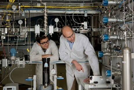
High Pressure FTS reactor Rig

Dr. Elbashir team designed and commissioned the High Pressure & Temperature Supercritical Fluid Fischer-Tropsch Reactor Unit.  This unit has been designed to support research activities in GTL (Fischer-Tropsch) and in petrochemicals catalysis.  This unit is unique in a way that it provides flexible operation with regards to selecting reactor type; fixed-bed reactor or Continuous Stirred Tank reactor and it is equipped with advanced features in terms of automation that are required for unattended operation and more importantly for safe running of high flow of Carbon Monoxide and Hydrogen at elevated pressures and temperatures. The design work and the orders of the pieces started at TAMUQ while the construction and the detailed work have been conducted by Xytel Inc., a company from South Carolina. The design and the construction of this unit have been funded by QNRF in a 2nd Cycle NPRP and by the Research & Graduate Studies in a special fund for major equipment. RGS also provided other supporting fund for the analytical equipment required for this unit to build a highly sophisticated set of Gas Chromatographs and fuel characterization set needed to identify all products collected at the effluent of this unit.

The FTS reactor is divided primarily into two sections: the Feed section and the reactor and separator sections. Other sub sections are: cold water circulator, air flow unit, vent system and GC units. For more information refer the P&ID provided by manufacturer. The flow diagram (PFD) is shown below:

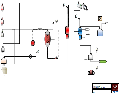
Gases are supplied to the reactor unit via 4 gas cylinders, at the start of the gas feed section. Solvents may be injected to the reactor via HPLC pump from the solvent tank located in the feed section. Solvent is vaporized in the pre-heater unit and mixed with the pre-heated gases in the pre-mixer before entering the fixed-bed reactor. Reactor pressure may be controlled via the Badger valve located downstream of the fixed-bed reactor. Two traps, hot and cold, are located downstream of the badger valve to separate the hot wax and liquids from the permanent gases respectively. Gas samples from the hot traps is analyzed in the online GC attached downstream of the hot trap. Total gas flow can be calculated from the Ritter meter located downstream of the cold trap. Was samples can be collected in the wax sample collector located just below the hot trap, while liquid samples are collected in a waste solvent tank just after the cold trap.

The reactor rig has undergone major modifications recently. More details about these modifications can be seen in the below slide.

Verified by ExactMetrics